Designing the rings was undertaken. Initial thoughts were for 1/2" wide rings connected to a hub via 1/2" wide axles. Maybe two or three axles similar to a wagon wheel. After seeing Weston Bye's magnetic clock I decided to use circles of metal to connect the outer ring with the inner hub. Shown below is a schematic of the proposed design. It is based on 1/16" thick sheet brass. The outer ring is 1/2" wide and the inner rings are 3/8" wide. The central hub is minimally a 1" diameter circle to support the hub already made. Since the schematic is the Mars ring the the hole in the center is 1/4"; this needs to be 1/4" to allow the Earth tube to pass.
The next challenge was determining how best to cut the rings from the sheet of brass purchased. This sheet is 12" X 12". It first needs to be cut into squares for each of the planet rings. Cutting the brass into smaller squares required purchasing some different blades for the scroll saw. 46 Tooth round blades were purchased from Lowes. This is plenty of teeth to cut such thin material with three teeth on the 1/16" of the brass at all times. In order to cut the rings from the squares using the rotary table in the mill a sacrificial support had to be devised. I decided to use some thin wood sheet stock laying around in the wood shop.
Clearly the sheet of brass is not quite large enough to fit both the Mars and the Earth rings: 7.364" + 5.016" = 12.380"! Another purchase from Speedy Metals!
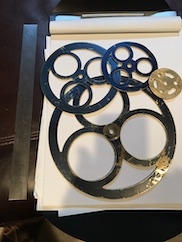
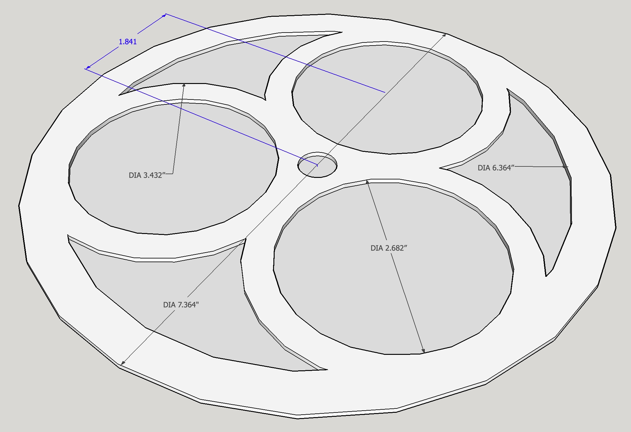
The planned OD's of the planet rings along with other parameters are listed in the table below. The "Support Circle" is the diameter of the circle that defines the location of the centers of the inner circles. Based on this value it is unclear whether the Mercury and the Venus rings can use circles for support. The "Gap Between Rings" applies to the current planet and the next planet in the table.
| Planet | Orbital Ratio | Orbital Diameter | Ring Width | Ring OD | Ring ID | Support Circle Diam | Gap Between Rings |
|---|---|---|---|---|---|---|---|
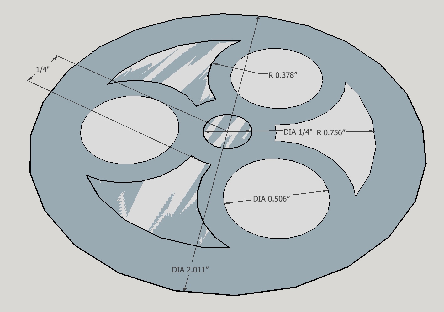
| Mercury | 0.39 | 1.761" | 1/4" | 2.011" | 1.511" | 1.255" | 0.865" |
| Venus | 0.72 | 3.251" | 3/8" | 3.626" | 2.876" | 1.938" | 0.39" |
| Earth | 1.00 | 4.516" | 1/2" | 5.016" | 4.016" | 2.508" | 1.348" |
| Mars | 1.52 | 6.864" | 1/2" | 7.364" | 6.364" | 3.682" |
The Earth ring is pictured next. The support circles are only 1/4" thick, which seems more appropriate on this smaller ring. This exposes the inner ring slightly, but this will probably be obscured by the width of the end mill cutting the opening.
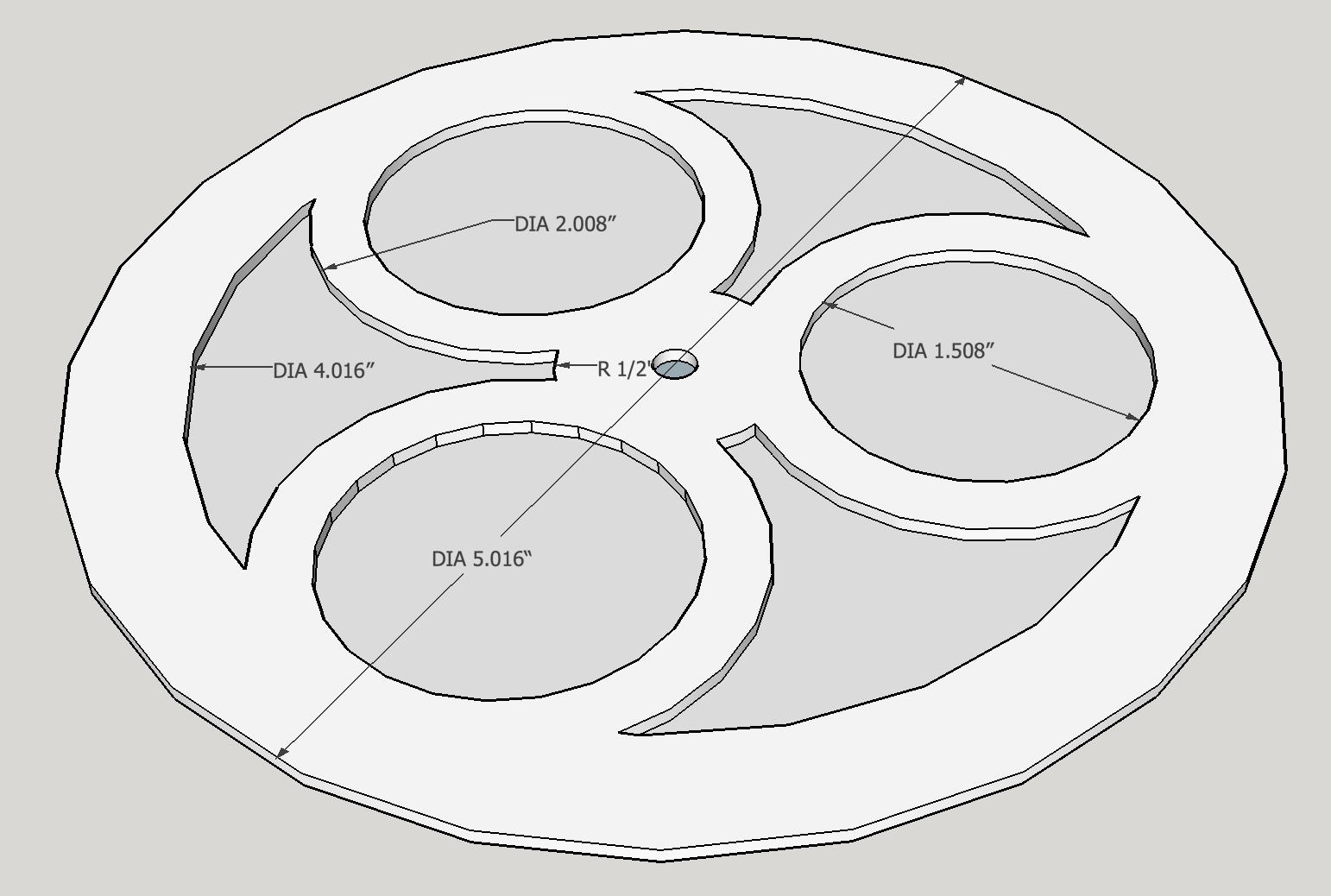
The Venus ring is pictured next. The support circles are again 1/4" thick. The inner ring is no longer exposed.
Finally, the Mercury is shown below. Note that the inner 'hub' is only 1/2" in diameter, unlike the other three planets whose hubs are 1" in diameter.
Tried to use the scroll saw with a spiral 46 tpi blade. This gives almost 3 teeth across the 1/16" thick brass sheet. It cut, but at a speed that would have taken a month to finish. A regular blade was little better, so switched to the coping saw and cut at an angle so more teeth were engaged at a time. A cut was made across the 12" sheet at 5.25" from the edge. A cut at right angles to the first at 5.25" gave a square sized for the earth ring. The remaining 6.75" was cut 3.75" from one side. This piece was cut again to make a 3.75" square for Venus. This leaves a 3" X 5.25" rectangle for Mercury.
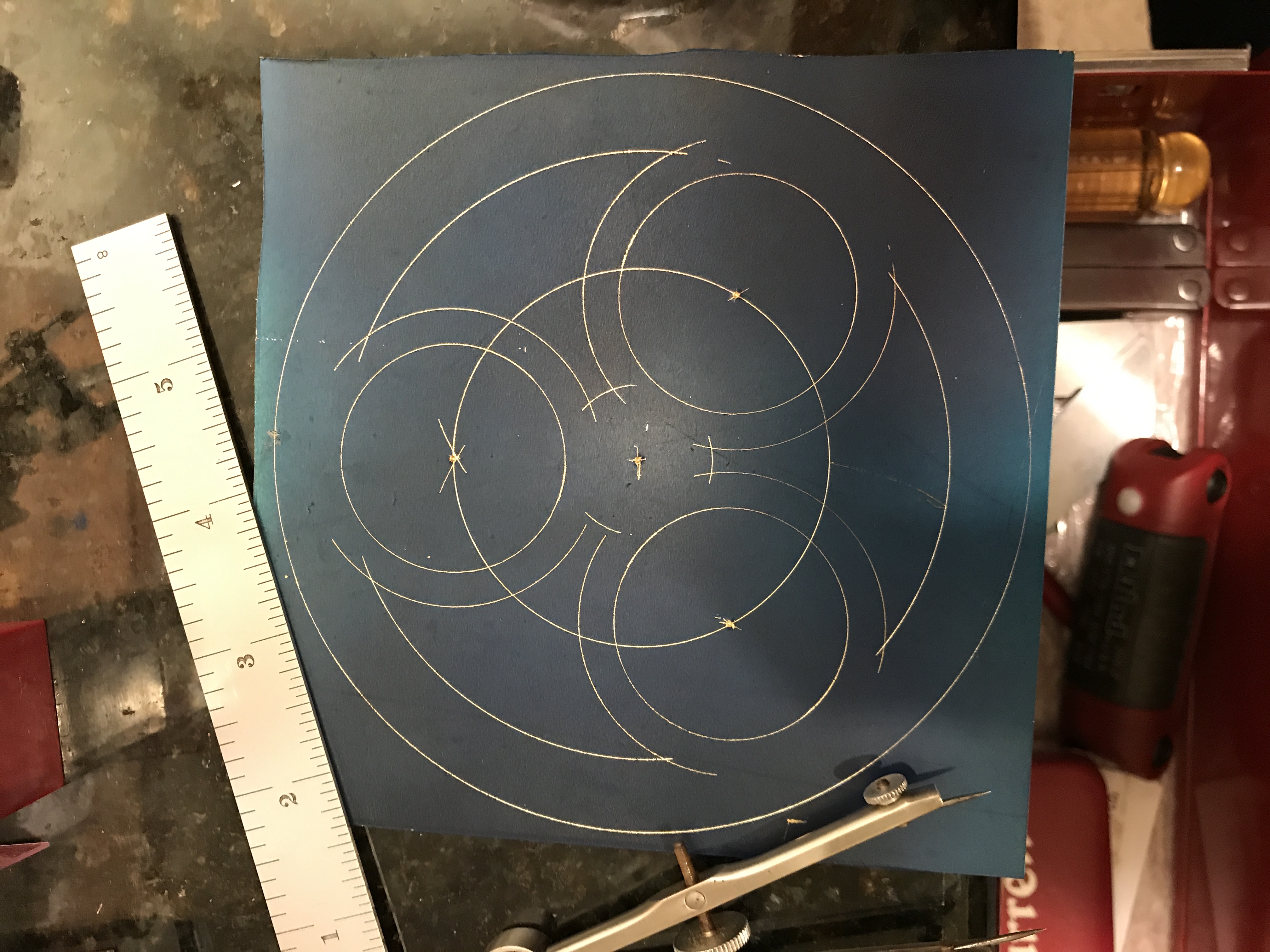
The Venus plate was marked out after 'blueing' with a Sharpie. The center was located and punched. The planet ring O.D. was then marked on the plate with a pair of calipers set at a 1.813" radius. The location circle defining the centers of the inner rings was also marked out with the calipers at radius 0.969". An equilateral triangle was then inscribed in the inner circle by the following process. The calipers were adjusted to the radius of the circle and one end was set on the circle. Two intersections with the circle were marked. The calipers were then adjusted to the distance between the two intersections just marked. This distance was used to mark the third intersection and could be checked against the same intersection as marked from the other of the two earlier intersections. The three intersections were center punched. These three punch marks are the centers of the inner circles and were used to mark out the inner and outer lines of the inner circles at radii of 0.469" and 0.719" respectively. Only segments of the outer circles were marked to minimize scratches in the final product. The ID of the planet ring (radius 1.439") was drawn; again in segments to minimize unnecessary scratches. Finally, arcs of the 1" inner ring were drawn as well completing the wedges that had to be removed.
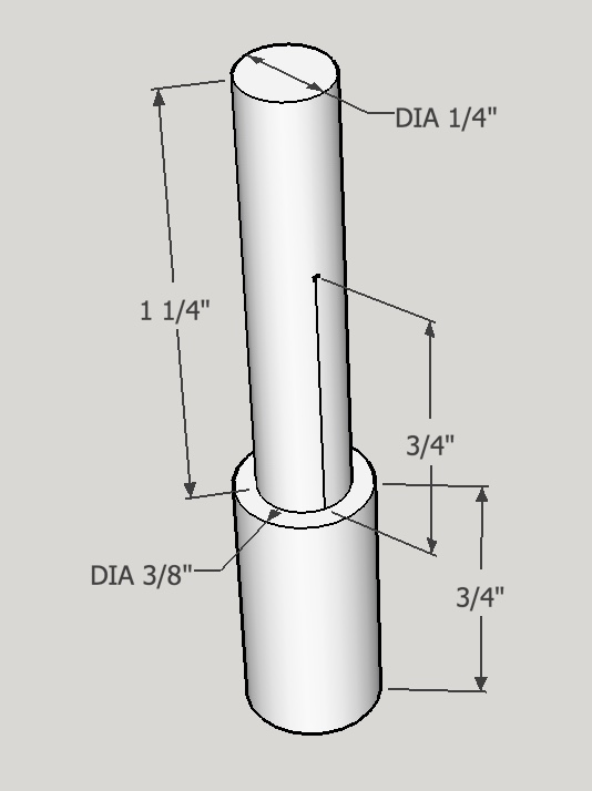
The plan of attack to produce this ring was as follows. The Sherline rotary table has a threaded hole in the center. I made a bolt to fit this hole that has been reduced to 1/4" for the top 1/2" and serves as a center locater. I found it necessary to put teflon tape around the bolt to make sure it was tightly held in the table. Consequently, 1/4" holes need to be drilled in the wood block that will hold the ring and in the ring itself at four places: the overall center and the three inner ring centers. The Mercury tube is 3/16" so it readily passes through the Venus ring and therefore will not be a problem. Double sided tape will be used to hold the plate to the wooden block for all milling operations. After drilling the holes the plate will be mounted on the rotary center and clamped in place. The appropriate radii will be set and the circles and circle segments will be milled with a 1/8" end mill. When necessary a 1/8" hole will be drilled through the plate as a start for the end mill.
And this is how the Venus ring was actually produced. A 1" X 3" X 3" block of wood (a cutout from the router table) was covered with two strips of double sided tape and the plate was firmly pressed onto the tape. The block of wood with plate was clamped to the mill table on two supports. The center hole punch was located with a center finder and it was then drilled with a center drill followed by a 1/4" drill bit. This was repeated for the other three punch marks. The tearout in the wood was cleaned up with the drill bit and some light sanding.
The rotary table was squared on the table and the center aligned with the spindle via the center finder. The hole in the block was a little tight for the alignment shaft, so the holes were all reamed with a 1/4" reamer and then fit snugly. The block was then clamped to the rotary table with a bolt through one of the inner circle center holes. The table was then moved out on the y-axis the radius of the outside of the planet ring plus one half of the diameter of the end mill: 1.813 + 0.0625 = 1.876" placing the outside edge of the end mill outside the circle to be cut. A lot of vibration in some places. With the one bolt one side of the plate is about 10-15 thou lower than the other. Of course, the plate slipped at one point!!! Was able to recover and completed the cut. Found some increased support was had with a 1/4" rod through brass and into wood. Need to rethink how best to secure work piece prior to proceeding.
Also realized the end mill was dull. Sharpened with all three diamond hones. Need to purchase more 1/8" end mills!!!
Decided to try with the one bolt and the center shaft. Recentered the work under the spindle and moved the table to the inside of the planet ring (1.439" - 0.063" = 1.376"). Aligned 1/8" rod held in the Jacob's chuck in order to keep the circumference within the lines of the wedge-shaped cutout. Drilled first with a center drill and then with a 1/8" drill bit. Then cut the outside of the 'wedges' with the end mill 0.005" per pass. The sharpened end mill worked much better and left clean sides to the groove.
The inner lines of the wedges were cut next. These align with the 1" O.D. inner hub of the planet ring. Consequently, the spindle was recentered over the center of the ring and then the y-axis of the table was moved 0.500" + 0.063" = 0.563" out.
Next the outside of the inner circles were cut to link the arcs made previously. The spindle was centered over the center of an inner circle center hole and then the y-axis was moved 0.719" + 0.063" = 0.782" to place the cutter just outside the arc. All six arcs were cleanly cut and the wedges came free.
The final cuts to be made were to remove the centers of the inner circles. I followed the same process as for the other cuts. The spindle was moved such that the end mill just touched the inside of the circle. The cut could only go about 300° around the circle before the ring ran into the back of the mill!! Consequently, these will probably need to be bored out.
Shades of things to come when cutting the larger planet rings.
Decided to try a different approach prior to drilling and boring. I have a riser block that can be used on the lathe or on the mill to provide more headroom. This was put in place, the head re-centered over the center of the circle, and the spindle was moved so that it rested in the previously slot. Milling then proceeded as before. This worked out well and all three inner holes were cut out. A little filing and a passable Venus ring is the result. May need to make a second as there are a few obvious mistakes, but the techniques worked perfectly.
A second Venus ring was made based on the learning from the first. All of the cuts were first aligned with the 1/8" end mill as this seemed more accurate than going by the measurements. The drilled holes were much better aligned with the internal cuts. All of the internal cuts were very clean and shiny. The outside cut was still a challenge. It might make sense to use a bigger end mill for future outside cuts on the planet rings and just work in from the outside corners.
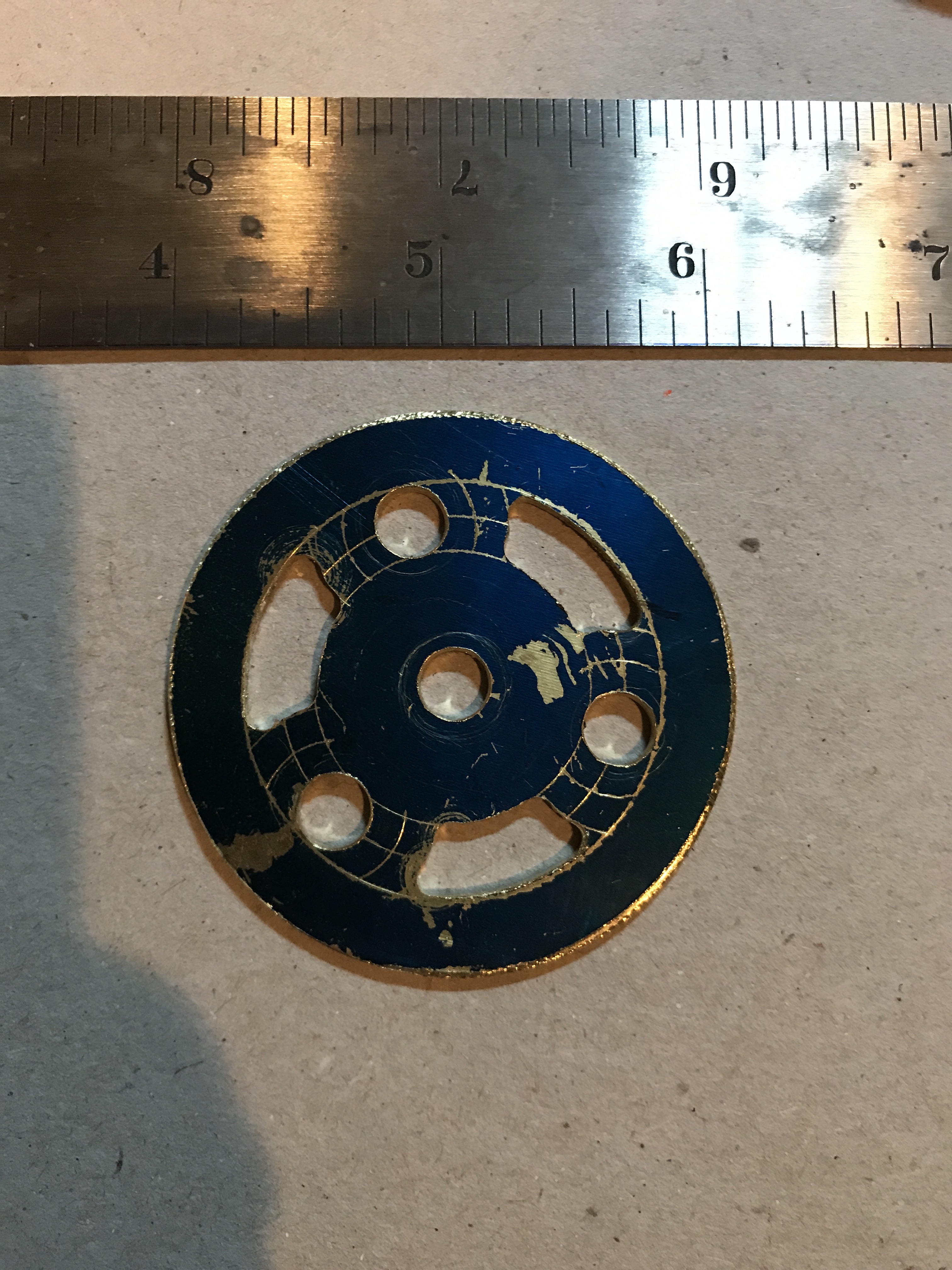
For the Mercury ring I took a small square of brass sheet, blued and marked out the various circles. There is just enough room to put a 1/4" drill bit between the outer ring and the inner. There did not seem to be any way to increase the size of the three circles beyond the 1/4" as they would cut into both the inner and the outer ring. Also the 'sides' could not be expanded as cutting would take place immediately next to the center pin holding the plate. Consequently, decided to leave the bars between the open wedges a little thicker than planned. Looks ok. The outside cut went ok with the out to in approach, but this might be a very long route to take with the Earth or Venus rings. The wedges were pretty straightforward as they were cut with two arcs and no sides. The ring was cleaned up with a file.
Decided to go with a full 1" diameter inner ring on the Mercury ring as the picture clearly shows. This could be changed at a later date if I so decide.
The Earth ring was next and a was cut from a 5 1/4" square piece of 1/16" brass sheet. The center hole was marked and punched. The outer ring was drawn with a compass set to 2.508". A circle was then drawn at 1.254" radius to lay out the centers of the support rings. Three corners of a triangle were marked as per the directions for the Venus ring. Each of these corners of a triangle were then center punched. With the compass set for 0.754" the three IDs of the support rings were drawn. Arcs were drawn at 1.004" for the outer sides of the support rings to delineate the wedges to be removed. Similarly, arcs were drawn at 0.5" radius from the center of the Earth ring and at 2.008" from this same center.
The four corners of the square, marked out stock were cut off with a hacksaw leaving an 'octaganoid' shape. The four holes were drilled as before with increasing drill sizes up to 1/4" and the hole exits were cleaned up by hand with a chamfer bit.
Instead of switching between a drill chuck and the mill collet holding an edge finder, I chucked the aluminum handled prick punch in the drill chuck to locate the hole centers. This probably halved the time required to drill the four marked holes.
Cutting went pretty much as before except it was more difficult to provide sufficient clamping when centered on a support hole. None of the remaining holes aligned with the tee slots in the rotary table. So had to use a strap clamp near the centered hole. This left the other side of the plate high causing chatter if the feed rate was too fast. A fine finish on the outside of the ring was obtained by taking a last pass without further advancement in climb milling mode. The inner arcs of the outer ring were cut first starting with drilled holes. A 3/16" to 1/8" fixture was used to align the spindle with the markings on the plate. The sides of the wedges were then cut followed by the insides of the support circles.
Finally, it was time for the Mars ring. A 7 1/2" square section of 1/16" brass plate was cut from a 12" X 12" purchase.
I was struggling to get the coping saw to cut, so I switched to cut off wheels on the Dremel. The holes in the wheels were too small so opened them with a 0.116" drill bit. Went through quite a few wheels, but cutting was successful.
The rings were marked out on the sheet after spraying with blue marking out paint. After marking the center the OD of the ring was marked at radius 3.682". The inner 0.5" radius circle was marked. Next the support circle (radius 1.841") was drawn and the centers of the three circles were marked as discussed above. Arcs were drawn at radius 1.716". Arcs to indicate the outer circle ID were also drawn at radius 3.182" from the center of the blank. Finally, the IDs of the inner circles were drawn at radius 1.341".
The corners of the square blank were marked for removal and cut off. I switched back to the coping saw after changing blades. It is faster then the cut off wheels in the Dremel, though more effort. This gave the familiar octagon ready for drilling and rotary table work in the mill. The four locations for drilling were center punched and drilled on the drill press. This was a necessity for the center hole as it could not be reached with the mill spindle.
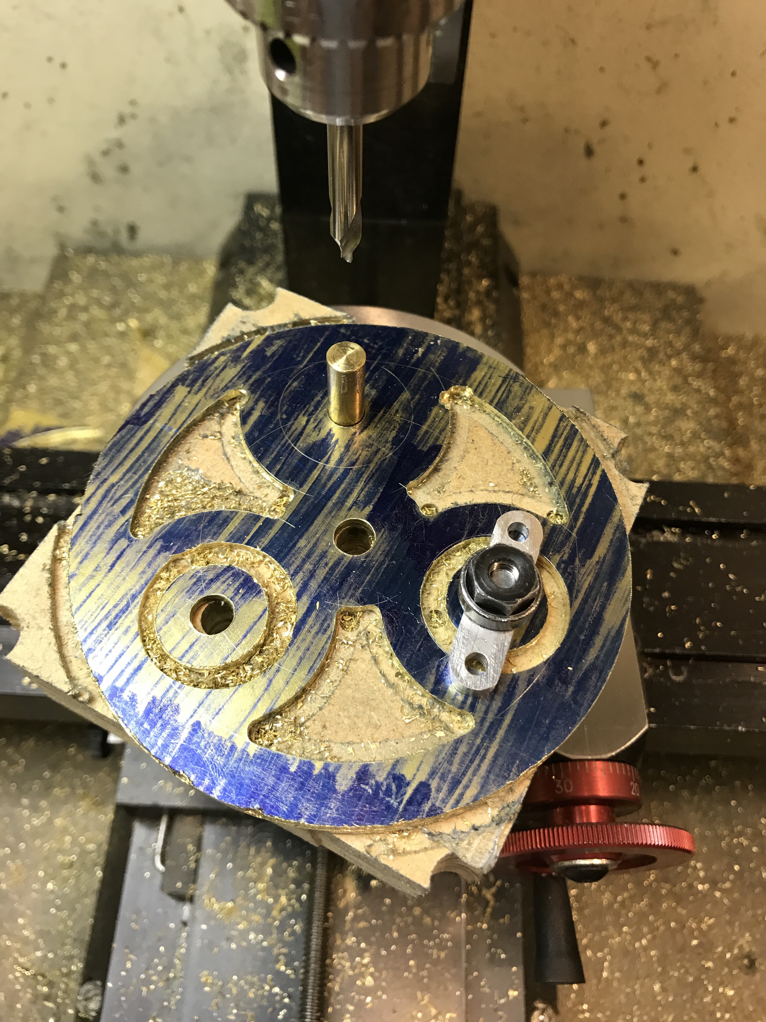
A 3/4" X 7" X 7" block was made for the Mars plate and drilled 1/4" for the four holes. The corners were cut off of he block to further reduce its size. The block was covered with double sided carpet tape and the plate was attached. Placing this on the rotary table highlighted the fact that there was no way to clamp the block and plate to the table.
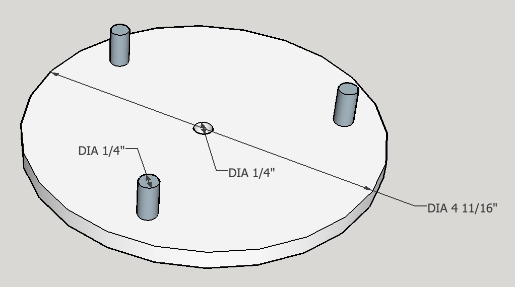
A simple clamping jig was devised consisting of two parts, a central double ended screw and a plate with three pins. The screw will fit the rotary table and be threaded 1/4-20 on the other end for a nut. This nut will hold down a plate that has three pins in it that align with the three support circle holes on the Mars ring.
Had a difficult time making the doubly threaded screw shown above. First, I tried cutting the threads on the lathe. The threads did not look great and a 3/8-16 nut did not fit. Grabbed a die to finish them and with some difficulty got it started and cut the threads only to discover that the die was left-handed. The only LH die I have and I pulled it out for this job!! So the second try I decided to just use a right-handed 3/8-16 die from the beginning. The threads were cut with effort holding the hex stock in the vise. The screw was quite bent!! So the third time I decided to return to cutting the threads on the lathe. I went ostensibly to 0.060" depth and a nut still did not fit. Grabbed a RH threaded die and went over the threads. The nut fits, but it is an ugly thread. The screw also fits nicely in the rotary table.
Decided to simplify the disk and just used 1/8" X 3/4" bar stock. Cut a 3" piece and drilled up to a 1/4" hole about 1/4" from the end. Placed this on the ring and marked a second hole. This hole was then drilled. A 1/4" pin was glued in this second hole. The first hole was fit over the center screw and the pin was inserted in one of the three drilled holes in the ring/wood base. This was held tightly to the rotary table with a nut on the central threaded screw. Attempted to cut the outer edge of the ring, but go significant movement of the ring relative to the table. Luckily one of of the three holes could be aligned with the very end of a tee slot in the rotary table and clamped tight. Cutting proceeded as usual on the OD.
Then drilled 1/8" and cut the ring ID parts of the wedges. Shifted the center to one of the support circle holes and clamped the middle hole with a screw in the tee slot. Was then able to cut the sides of the wedges. This was repeated for the other two support holes.
Used a double ended 1/8" end mill that I don't believe had ever been used before. It was quite sharp leading to a much easier cut. Should have cut the OD with this end mill and save myself significant time.
Explored a number of possibilities for cutting the inner circle IDs. The first to be considered was pinning the center hole on the milling table, not in the center but in a slot the inner circle radius from the center of the rotary table. The workpiece would be free to rotate around this hole. The center of the inner hole to be cut would hold a tight pin that was constrained from below to follow a circle, also with a radius equal to the inner circle radius. In this fashion all point on the workpiece would describe a circle when the rotary table was turned. The only problem that was left unsolved was some means of holding the workpiece down.
After struggling with this for some time I looked for some way to cut the holes on South Bend lathe. Saddle boring came to mind and I found an article in "Model Engineering Workshop" issue 40 that described saddle boring including the construction of two boring bars. I went with the simpler, nonadjustable, of the two. Its plans and construction are covered here.
Before beginning the saddle boring the holes need to be opened to 1". The lathe milling table was installed on the cross slide by loosening the two set screws. The table was inserted and the screws tightened. Since the small angle plate was to be used and its slots are 1" apart, it was necessary to tap a few more holes 3/8-16. The angle plate was then bolted to the table with 1 1/4" long screws. The center hole of the ring mounted on its wooden block was bolted to the top of one of the vertical slots in the angle plate. The inner circle hole was set at center height using a 1/4" drill bit mounted in the chuck. The hole was then opened in 1/16" increments from 1/4" to 1" diameter. It was necessary to move the carriage very slowly into the drill bit and apply cutting fluid.
The boring bar was set in place without moving the ring. The carriage was locked both at the handle on the back of the taper attachment and the two screws on the taper attachment. The small cutter was placed in the bar centered and a "zero" pass was made. The cutter was then moved in increments of 1/64 - 1/32". It was tighter than expected in the bar and had to be tapped with a hammer to move it. Each pass was taken very slowly and then through the wood. At one point the cutter could no longer pass completely through the wood as the angle plate was in the way. There was significant shaking as the cutter moved into the second half of the plate. This may have been due to the ring not being square vertically. Will need to double check the next hole for alignment in this direction.
The changes in depth of cut were "measured" with the use of a depth gauge. Either the back of the cutter protruding or the depth of the back of the cutter was set on the depth gauge and this was measured with a ruler.
When there was about 1/2" of radius remaining (the hole was about 1 1/2" ID) the small cutter was removed and the larger cutter (1 5/8") was set in the bar and set to just touch the ID of the circle. Cutting then proceeded similarly to the smaller cutter. Cutting was stopped when the markout line was reached.
One of the three holes complete and it only took most of a day! The next two should be quicker with this experience behind me.
Not so fast there pardner! The second hole drilling went quickly, but the boring with the longer bit was really vexing. So part way through an extra clamp was added. A bar clamp was used to hold the front side of the ring to the table. The bar clamp handle sat right in front of the tailstock so two /64" holes were drilled through the handle for a 1/8" johnny bar. The plate had to be recentered vertically and the bit went back to the grinder and the diamond hones. Boring then proceeded uneventfully at 1/64" passes. Two complete!
The third hole actually went fairly uneventfully. Honed both bits prior to starting and kept the cuts to 1/64". Really only got significant chatter near the end of the longer bit when it was fully extended. Removed the Mars ring from the block (watch out for bending) and cleaned up all of the edges with a file. Just need to sand and polish the rings to a nice finish.